
Yes, I think it's a good idea to experiment with caps. Geofex has tons of good info on guitar effect, especially in the "technology of" and FAQ. Entire cultures have been destroyed by fighting over which capacitor is best.ĮSP has pages on capacitors and filters along with much else in the articles and projects pages. This site has a bunch of good info on the application of filters in a musical setting,Ĭapacitors are the basis for religious wars. The basic reasons for using particular types of filters is the same in both domains though. I came to doing audio from DSP, so my foundation in filters is actually in the digital world. Here is a three part app note called An Audio Circuit Collection. All of it is available on TI's website now.

TI and National Semi put out bunches of app notes on filter design. There's a vast library available on the design of op amp filters. I think the best way to learn those is just look at schematics of the effects you are interested in and then breadboard the parts of the circuit to manipulate them and hear what they do. The classic guitar filters were be done in some interesting/ingenious ways. It depends on what type of filter you want to build. I didn't find that to be true of any of the 1044 or 7660 devices even with the boost pin used.įilters are a big subject. They have more current capacity are more efficient and have a switching frequency that is above the audible range. The + input in this case is referenced to ground.Īnother note, my personal preference is for the LT1054 for the voltage converter. On the schematic, you are looking at using IC1A as an inverting amp or filter structure? If so, you most likely don't want Vb. Some of this stuff is directly applicable to clean guitar preamp circuits for example.
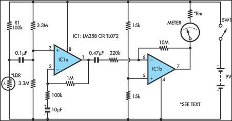
IC1A OP AMP HOW TO
Good examples of how to filter for hi-fi applications can be found by looking into the DIY headphone amplifier community. How much you do depends on the application. remembering that the ground is more positive than the negative rail).

Once you are using split rail designs, you can filter the negative supply in exactly the same way you filter the positive supply (with the polarized caps and such oriented the right way, i.e. But, ground is always separate from the -9V rail and the audio signal is referenced to ground. There are other things that will get hooked to ground. I won't say though that the only thing going to -9V is the op amp lower supply. The -9V is a separate power rail from ground. In a split power supply (dual rails, +9V and -9V), ground is still ground. It allows you to filter the power to both rails at the op amp as well. Also, some op amps just work better in a split rail setting. Cascaded filter circuits are much simpler if you don't have to have coupling caps in-between every stage. The advantage in the -9V to +9V is that it simplifies many circuits. TI has a mass of publicly available application notes on op amps too that are a great resource.Īs far as headroom goes, 18V is 18V. There's more to it than that though and you will have to spend time with the spec sheets if you want to get in depth with it. FET inputs imply higher input impedance and BJT outputs imply more current drive. But, as a general rule, op amps behave like the transistors that make them. For the current and impedance questions, you pretty much have to go to the spec sheets.


 0 kommentar(er)
